Technique Parameter
| Measurement range | -50~100℃ |
| -20~50℃ | |
| Accuracy | ±0.5℃ |
| Power supply | DC 2.5V |
| DC 5V | |
| DC 12V | |
| DC 24V | |
| Other | |
| Out-put | Current: 4~20mA |
| Voltage: 0~2.5V | |
| Voltage: 0~5V | |
| RS232 | |
| RS485 | |
| TTL Level: (frequency; Pulse width) | |
| Other | |
| Line length | Standard: 10 meters |
| Other | |
| Load capacity | Current output impedance≤300Ω |
| Voltage output impedance≥1KΩ | |
| Operating environment | Temperature: -50℃~80℃ |
| Humidity: ≤100%RH | |
| Produce weight | Probe 145 g, with collector 550 g |
| Power dissipation | 0.5 mW |
Calculation Formula
Voltage type (0~5V): T=V / 5 × 70 -20 (T is the measured temperature value (℃), V is the output voltage (V), this formula corresponds to the measurement range -20 ~ 50 ℃) T=V / 5 × 150 -50 (T is the measured temperature value (℃), V is the output voltage (V), this formula corresponds to the measurement range -50 ~ 100 ℃) Current type (4~20mA) T=(I-4)/ 16 × 70 -20 (T is the measurement temperature value (℃), I is the output current (mA), this type corresponds to the measurement range -20 ~ 50 ℃) T=(I-4)/ 16 × 150 -50 (T is the measured temperature value (℃), I is the output current (mA), this formula corresponds to the measurement range -50 ~ 100 ℃) Note: The calculation formulas corresponding to different signal outputs and different measurement ranges need to be recalculated!Wiring Method
1. If equipped with a weather station produced by our company, directly connect the sensor to the corresponding interface on the weather station using the sensor cable. 2. If the transmitter is purchased separately, the matching cable sequence of the transmitter is:| Line color | Output signal | ||
| Voltage type | Current type | Communication type | |
| Red | Power+ | Power+ | Power+ |
| Black (green) | Power ground | Power ground | Power ground |
| Yellow | Voltage signal | Current signal | A+/TX |
| Blue |
|
| B-/RX |
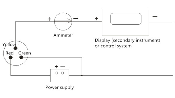
3. Transmitter voltage and current output wiring:
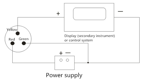
Wiring for voltage output mode
Wiring for current output mode

(Water temperature sensor)
MODBUS-RTUProtocol
1. The serial format Data bits 8 bits Stop bit 1 or 2 Check Digit None Baud rate 9600 Communication interval is at least 1000ms 2. Communication format [1] Write device address Send: 00 10 Adress CRC (5 bytes) Returns: 00 10 CRC (4 bytes) Note: 1. The address bit of the read and write address command must be 00. 2. Adress is 1 byte and the range is 0-255. Example: Send 00 10 01 BD C0 Returns 00 10 00 7C [2] Read device address Send: 00 20 CRC (4 bytes) Returns: 00 20 Adress CRC (5 bytes) Explanation: Adress is 1 byte, the range is 0-255 For example: Send 00 20 00 68 Returns 00 20 01 A9 C0 [3] Read real-time data Send: Adress 03 00 00 00 02 XX XX Note: as shown below:| Code | Function definition | Note |
| Adress | Station number (address) |
|
| 03 | Function code |
|
| 00 00 | Initial address |
|
| 00 01 | Read points |
|
| XX XX | CRC Check code,front low later high |
| Code | Function definition | Note |
| Adress | Station number (address) |
|
| 03 | Function code |
|
| 02 | Read unit byte |
|
| XX XX | Soil temperature data (high before, low after) | Hex |
| XX XX | Soil humidity data (high before, low after) |
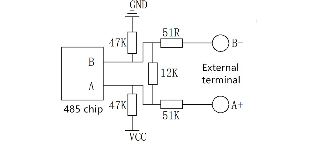
RS485 Circuit
Instructions for use
Connect the sensor according to the instructions in the wiring method, and then insert the sensor probe into the soil to measure the temperature, and supply power to the collector and the sensor to obtain the water temperature at the measurement point.Precautions
1. Please check whether the packaging is intact and check whether the product model is consistent with the selection. 2. Do not connect with power on, and then power on after checking the wiring. 3. Do not arbitrarily change the components or wires that have been soldered when the product leaves the factory. 4. The sensor is a precision device. Please do not disassemble it by yourself or touch the surface of the sensor with sharp objects or corrosive liquids in order to avoid damaging the product. 5. Please keep the verification certificate and certificate of conformity, and return it with the product when repairing.Troubleshooting
1. When the output is detected, the display indicates that the value is 0 or is out of range. Check whether there is obstruction from foreign objects. The collector may not be able to obtain the information correctly due to wiring problems. Please check whether the wiring is correct and firm. 2. If it is not the above reasons, please contact the manufacturer.Structure Size
Sensor Size
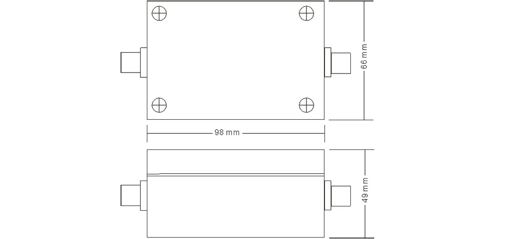
(Water temperature sensor)
Selection table
| Number | Power supply mode | Output signal | Explain |
| LF-0020 |
|
| Water temperature sensor |
|
| 5V- |
| 5V powered |
| 12V- |
| 12V powered | |
| 24V- |
| 24V powered | |
| YV- |
| Other powered | |
|
| 0 | No change | |
| V | 0-5V | ||
| V1 | 1-5V | ||
| V2 | 0-2.5V | ||
| A1 | 4-20mA | ||
| A2 | 0-20mA | ||
| W1 | RS232 | ||
| W2 | RS485 | ||
| TL | TTL | ||
| M | Pulse | ||
| X | Other | ||
| For example: LF-0020-24V-A1: water temperature sensor (transmitter) 24V power supply, 4-20mA output | |||