Product Instruction
The new-generation PHTRSJ soil pH sensor solves the shortcomings of traditional soil pH that requires professional display instruments, tedious calibration, difficult integration, high power consumption, high price, and difficult to carry. ● New soil pH sensor, realizing online real-time monitoring of soil pH. ● It adopts the most advanced solid dielectric and large-area polytetrafluoroethylene liquid junction, which is not easy to block and maintenance-free. ● High integration, small size, low power consumption, easy to carry. ● Realize low cost, low price and high performance. ● High integration, long life, convenience and high reliability. ● Simple operation. ● Support secondary development. ● The electrode uses high-quality low-noise cable, which can make the signal output length up to 20 meters without interference. This product can be widely used in the fields of agricultural irrigation, flower gardening, grassland pasture, rapid soil testing, plant cultivation, scientific experiments and so on.Calculation Formula
Voltage type (0 ~ 5V output): D = V / 5 × 14 (D is the measured pH value, 0.00pH≤D≤14.00pH, V is the output voltage (V)) Current type (4 ~ 20mA output): D = (I-4) / 16 × 14 (D is the measured pH value, 0.00pH≤D≤14.00pH, I is the output current (mA))Wiring Method
(1) If equipped with a weather station produced by our company, directly connect the sensor to the corresponding interface on the weather station using a sensor line. (2) If the transmitter is purchased separately, the cable sequence of the transmitter is:| Line color | Output signal | ||
| Voltage type | Current type | Communication type | |
| Red | Power + | Power + | Power + |
| Black (green) | Power ground | Power ground | Power ground |
| Yellow | Voltage signal | Current signal | A+/TX |
| Blue |
|
| B-/RX |

MODBUS-RTU Protocol
1. The serial format Data bits 8 bits Stop bit 1 or 2 Check Digit None Baud rate 9600 Communication interval is at least 1000ms 2. Communication format [1] Write device address Send: 00 10 Adress CRC (5 bytes) Returns: 00 10 CRC (4 bytes) Note: 1. The address bit of the read and write address command must be 00. 2. Adress is 1 byte and the range is 0-255. Example: Send 00 10 01 BD C0 Returns 00 10 00 7C [2] Read device address Send: 00 20 CRC (4 bytes) Returns: 00 20 Adress CRC (5 bytes) Explanation: Adress is 1 byte, the range is 0-255 For example: Send 00 20 00 68 Returns 00 20 01 A9 C0 [3] Read real-time data Send: Adress 03 00 00 00 01 XX XX Note: as shown below:| Code | Function definition | Note |
| Adress | Station number (address) |
|
| 03 | Function code |
|
| 00 00 | Initial address |
|
| 00 01 | Read points |
|
| XX XX | CRC Check code, front low later high |
| Code | Function definition | Note |
| Adress | Station number (address) |
|
| 03 | Function code |
|
| 02 | Read unit byte |
|
| XX XX | Data (high before, low after) | Hex |
| XX XX | CRCCheck code |
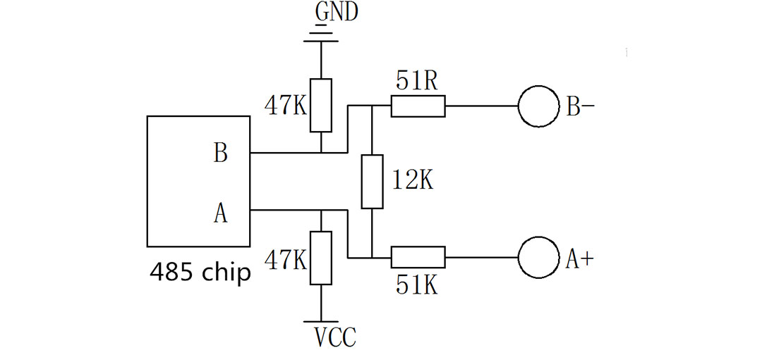
RS485 circuit
Instructions for use
1. When the sensor leaves the factory, the probe is provided with a transparent protective cover, and the built-in protective liquid protects the probe. When using, please remove the protective cover, fix the filter tank and the sensor, and then use the attached cable tie to wrap the filter in the filter tank. To prevent direct contact between the soil and the probe and damage the probe. In actual use, please ensure that the filter trough and the filter are firmly connected. Do not remove the filter trough and the filter. Insert the probe directly into the soil to avoid making the probe damage and unrepairable. 2. Insert the probe part vertically into the soil. The depth of the probe must be at least covered by the filter. Under normal circumstances, the pH in the air is between 6.2 and 7.8. 3. After burying the sensor, pour a certain amount of water around the soil to be measured, wait for a few minutes, and wait for the water to soak into the probe, then you can read the data on the instrument. Under normal circumstances, the soil is neutral and the pH is between Around 7, the actual pH value of the soil in different places will be different, it should be determined according to the actual situation. 4. The user can use the attached 3 pH reagents and configure according to the configuration method to check whether the product performance is normal.Precautions
1. In the pipeline in order to ensure the correct electrode measured pH value should be avoided during the measurement of air bubbles caused by inaccurate data; 2. Please check whether the packaging is intact and check whether the product model is consistent with the selection; 3. Do not connect with power on, and then power on after checking the wiring. 4. Do not arbitrarily change the components or wires that have been soldered when the product leaves the factory. 5. The sensor is a precision device. Please do not disassemble it by yourself or touch the surface of the sensor with sharp objects or corrosive liquids during use to avoid damaging the product. 6. Please keep the verification certificate and certificate of conformity, and return it with the product when repairing.Troubleshooting
1. For analog output, the display indicates that the value is 0 or is out of range. The collector may not be able to obtain the information correctly due to wiring problems. Please check whether the wiring is correct and firm, and the power voltage is normal; 2. If it is not the above reasons, please contact the manufacturer.Technique Parameter
| Measuring range | 0-14pH |
| Accuracy | ± 0.1pH |
| Resolution | 0.01pH |
| Response time | <10 seconds (in water) |
| Power supply mode | DC 12V |
| DC 24V | |
| Other | |
| Output form | Voltage: 0~5V |
| Current: 4 ~ 20mA | |
| RS232 | |
| RS485 | |
| Other | |
| Instrument Line length | Standard: 5 meters |
| Other | |
| Working environment | Temperature 0 ~ 80 ℃ |
| Humidity: 0 ~ 95% RH | |
| Power consumption | 0.2W |
| Housing material | waterproof plastic shell |
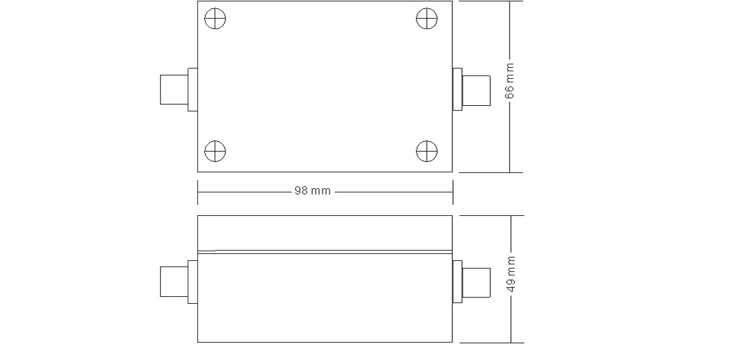
| Transmitter size | 98 * 66 * 49mm |
Wiring Method

Maintenance
1. The input end of the instrument (measuring electrode socket) must be kept dry and clean to prevent dust and water vapor from entering. 2. Avoid long-term immersion of electrodes in protein solution and acid fluoride solution, and avoid contact with silicone oil. 3. After long-term use of the electrode, if the slope is slightly reduced, the lower end of the electrode can be immersed in a 4% HF solution (hydrofluoric acid) for 3 to 5 seconds, then washed with distilled water and then immersed in 0.1mol / L hydrochloric acid Refresh the electrode. 4. In order to make the measurement more accurate, the electrode must be calibrated frequently and washed with distilled water. 5. The transmitter should be placed in a dry environment or a control box to avoid meter leakage or measurement error caused by water droplets splashing or being wet.