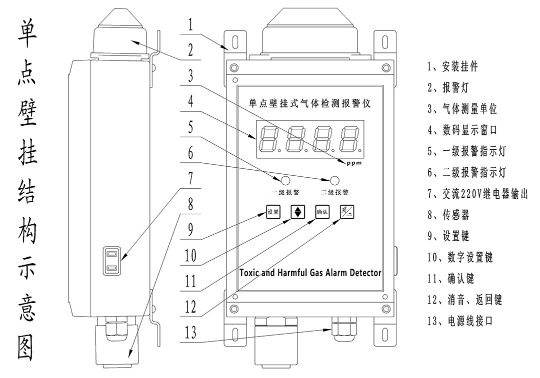
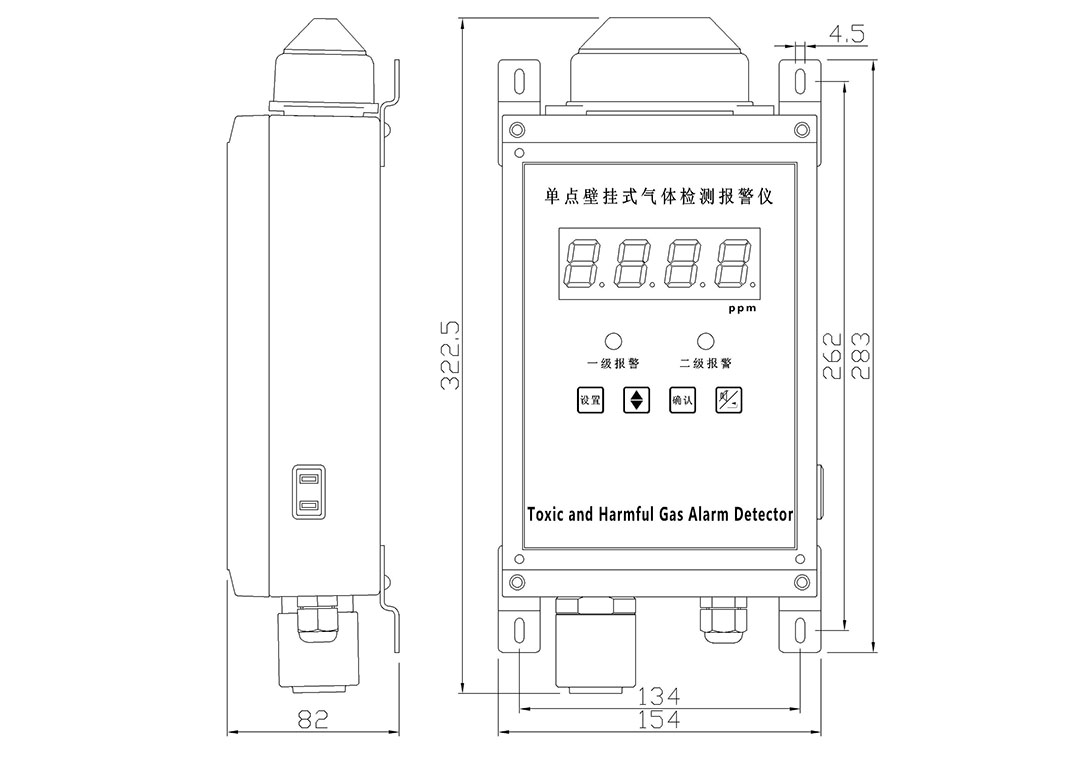
Structure chart
Technical parameter
● Sensor: electrochemistry, catalytic combustion, infrared, PID...... ● Responding time: ≤30s ● Display mode: High brightness red digital tube ● Alarming mode: Audible alarm -- above 90dB(10cm) Light alarm --Φ10 red light-emitting diodes (leds) and external strobe lights ● Output control: AC220V 5A Active switch output ● Work pattern: continuous operation ● Working power: AC220V ● Temperature range:-20℃ ~ 50℃ ● Humidity range:10 ~ 90% (RH) No condensation ● Installing mode: wall-mounted installing ● Outline dimension: 230mm×150mm×75mm ● Weight: 1800gTechnical parameters of gas-detecting
Product configuration
1. Wall-mounted detecting alarm: one 2. Certificate: one 3. Manual: one 4. Installing component: oneTable 1: Technical parameters of gas-detecting
| Gas | Gas name | Technical index | ||
| Measurement range | Resolution | Alarm point | ||
| CO | Carbon monoxide | 0-2000pm | 1ppm | 50ppm |
| H2S | Hydrogen sulfide | 0-100ppm | 1ppm | 10ppm |
| EX | Combustible gas | 0-100%LEL | 1%LEL | 25%LEL |
| O2 | Oxygen | 0-30%vol | 0.1%vol | Low 18%vol High 23%vol |
| H2 | Hydrogen | 0-1000pm | 1ppm | 35ppm |
| CL2 | Chlorine | 0-20ppm | 1ppm | 2ppm |
| NO | Nitric oxide | 0-250pm | 1ppm | 35ppm |
| SO2 | Sulfur dioxide | 0-20ppm | 1ppm | 5ppm |
| O3 | Ozone | 0-50ppm | 1ppm | 2ppm |
| NO2 | Nitrogen dioxide | 0-20ppm | 1ppm | 5ppm |
| NH3 | Ammonia | 0-200ppm | 1ppm | 35ppm |

Construction and installing

Operation instruction
After installation and powered on,it will display the gas type, first alarm, second alarm and measuring range. After the countdown of 30S, the instrument will directly enter the working state. It has been calibrated before delivery. If it is not necessary to change the alarm parameters, the following operation is not required. The single-point wall-mounted panel consist of the concentration indicated digital tube, the first alarm indicator, the second alarm indicator and 4 buttons. The buttons from left to right are: Setting button
  Up / Down button
  Confirmation button
  Mute / Back to the former menu Functional specification 1. Set the first and second alarm values, for oxygen alarm values is the upper and lower. 2. Restore factory Settings 3. The alarm sound can be eliminated in real time. The alarm sound will automatically start when the next alarm is given, without manual start. 4. When the gas concentration is greater than the first-level alarm value, the relay is sucked in, the buzzer alarms, and the first-level alarm indicator light is on. The state of relay is not changed when the noise is silenced in real time. 5. When the gas is combustible and the concentration exceeds 100%LEL, the instrument will automatically turn off the gas detector. 6. When menu stop operation,will automatic exit menu after 30S. Menu operation 1. Operate steps Enter the working state and display the detected value of the connected sensor. Setting parameters: Step 1: Press button
  , display 0000, first nixie tube flashing
 Step 2: Enter password 1111 (user password), press button
  to select one digit from 1 to 9 digits, then press button
 to select the next digit in turn (corresponding digit flashing), and then press button
 to select digits. Step 3: After the password input, press button
  and display F-01. You can select from F-01 to F-06 by pressing button
 . The details of functions F-01 to F-06 refer to table 2. For example, after selecting the function F-01, press button
 to enter the first-level alarm setting, and the user can set the first-level alarm. After the completion of setting, press button
 the instrument will display F-01. If other parameters need to be set as above, otherwise, you can press button
 exit this setting. Table 2: Functions F-01 to F-06 declaration
 | Function | Declaration |
| F-01 | First alarm value |
| F-02 | Second alarm value |
| F-03 | Range(Read only) |
| F-04 | Resolution(Read only) |
| F-05 | Unit(Read only) |
| F-06 | Gas type(Read only) |
 By pressing button
  to change value, by button
  to switch the position of the digital tube flashing. Press button
 to save Settings. If the gas is oxygen, the first alarm value is the lower limit of alarm. F-02 Second alarm value By pressing button
  to change value, by button
 to switch the position of the digital tube flashing. Press button
 to save Settings. If the gas is oxygen, the first alarm value is the lower limit of alarm. F-03 Range(Read only) Displays the maximum range of the Instrument. F-04 Resolution(Read only) 1 is an integer, 0.1 has one decimal place, and 0.01 has two decimal places.
  F-05 Unit(Read only) P indicate ppm, L indicate %LEL, U indicate %vol

 F-06 Gas type(Read only) The code for defining the common gas types,show in table 3 (Will use when the product is upgraded with communication function). Table 3 gas type code description
 | O2 | CO | H2S | N2 | H2 | CL2 |
| GA00 | GA01 | GA02 | GA03 | GA04 | GA05 |
| SO2 | NO | NO2 | HCHO | O3 | LEL |
| GA06 | GA07 | GA08 | GA09 | GA11 | GA11 |
3. Special function description Enter button  to input the password "1234", press button
 to enter the menu, now the menu will add P-01, A-01 and A-02. P-01 Parameter recovery S-01: Restore factory settings. During operation, users can restore factory Settings if the parameter Settings are abnormal. S-02: Factory calibration is completed. A-01/A-02Relay setting The board defaults to output by one relay, the user can set it through A-01. The menu structure is shown as below
 After pressing button
 to enter A-01 menu, will display F-01, it is Relay output mode setting, the default is LE level output, press button
  to change PU, PU is pulse output, Press button
  to save, then return to the menu F-01. Press button
 to switch menu,showing F-02 is the relay pulse output time setting, the default is 3 seconds, can be set to 3~9 seconds, press button
  to save settings after the completion of time input, press button
  to exit settings. Note: by default, this instrument only carries one relay, and users can choose to carry two relays. At this time, A-02 is set effectively, and the setting method is the same as A-01.
Others
1. For the wall-mounted combustible gas detect alarm, when the concentration of combustible gas exceeds 100% LEL, the system will automatically turn off the power supply, to make the detector stop working and realize the explosion-proof function. At this time, the digital tube will always display 100, the normally open switch end of the relay is connected, two light-emitting diodes flicker, the buzzer alarm. At this point, you can press button , the system will automatically exit the over-protection state, but if the gas concentration is still very high, the system will remain in this state. You can also turn off the power and wait for the gas concentration to drop before switching on the power to continue using. 2. After the first energization of the instrument, the sensor will have a polarization time. Generally, detecting gas takes several minutes,the polarization time of NO, HCL and other gases is relatively long. After the polarization is completed, the display value will gradually stabilize at 0, and then the instrument can enter into the normal detection state.Please pay attention to the user when using. Tip: electrify time should be some longer in winter, can be used after the sensor’s temperature come up.
Warranty Description
The warranty period of the gas detection instrument produced by my company is 12 months and warranty period is valid from the date of delivery. Users shall comply with the instructions. Due to the improper use, or poor working conditions, the instrument damage caused is not in the scope of the warranty.Important Tips
1. Before using the instrument, please read the instructions carefully. 2. The use of the instrument must be in accordance with the rules set in the manual operation. 3. The instrument maintenance and replacement of parts should be processed by our company or around the pit. 4. If the user is not in accordance with the above instructions to boot repair or replacement parts, the reliability of the instrument shall be the responsibility of the operator 5. The use of the instrument should also abide by the relevant domestic departments and factory equipment management laws and rules.